6' x 4' Single Axle Trailer
Drawbar Components
This section covers the all important drawbar angle gussets which provide additional strength to the drawbar as well as preventing metal fatigue as the drawbar does its work. Also in this section is the coupling mount, and the fitting of conduit tubing for later fitting of the lighting wiring.
DRAWBAR ANGLE GUSSETS
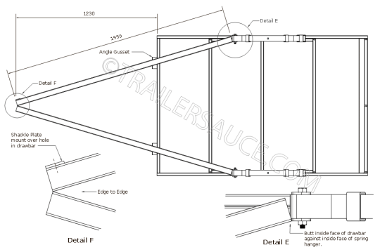
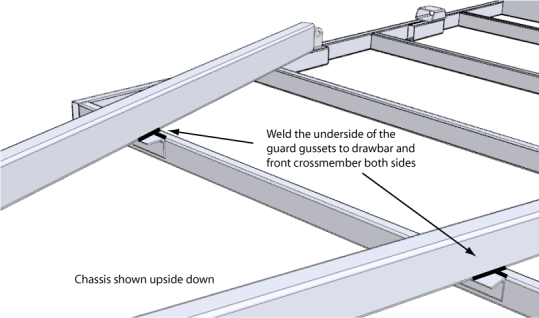
Where the drawbar meets the front crossmember, fit a piece of angle 40 x 5mm approximately 100mm long over the exposed section and weld around the angle on the crossmember (Never weld across the top of the drawbar) and a couple of welds under the angle gusset where the top edge of the drawbar meets. Round off the outside edges to prevent any injury to your shins.
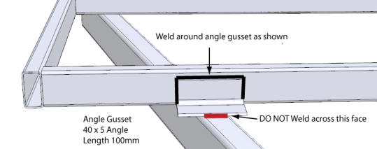
The angle gusset will give the drawbar and chassis a stronger and stiffer structure at this point.
TOPSIDE
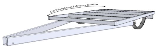
Double check all the welds on the drawbar and chassis and grind/buff any sharp burrs and edges before flipping the trailer right way up.
Sit the chassis on your stands or trestles and run an eye along the length of the chassis frame and check that the frame is level and straight. Any extreme twisting of the frame will need to be heat shrinked to correct before continuing. Twisting or bending of the frame normally occurs when there has been too much heat applied through welding on a poorly clamped chassis.
To correct any major twisting, weld up the top of the chassis where the welds are missing (don't weld along the front chassis crossmember and drawbar), recheck any twisting and mark where the centre of any bending is occurring. Using a oxy/acetylene/propane torch heat the side that needs to be shrunk and once nice cherry red, quench quickly with cold water. This will cause the steel to change structure and shrink hopefully correcting the problem.
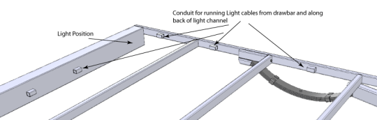
LIGHTING CONDUIT
Once all the welds have been laid, cut short sections of pipe(9/16" thin wall tube or similar) or small box section (25 x 25mm) around 40mm long and run these down one side of one of the chassis rails at regular intervals of around 200-300mm apart from the inside end of the drawbar back, and also along the back of the light channel. These pieces of pipe will be your conduit for running your lighting cable along the trailer and will support and protect the cable.
COUPLING PLATE
With the trailer right way up we can weld on the coupling plate. Ideally the plate will be 10-12mm thick for a standard lever style coupling and pre drilled to the coupling hole profile.
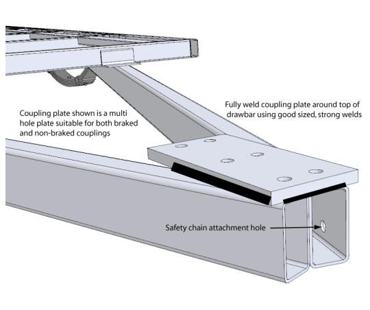
Position the coupling plate over the end of the drawbar so it extends 10-20mm over the end and centre and square it to the chassis before tacking. Check through the coupling plate holes that if there is enough clearance for the coupling bolts (including enough room to turn the nuts) to be fitted inside the "A" frame section of the drawbar. Adjust the coupling plate position if required.
Fit the coupling loosely and check that the lever operates correctly.
Take a couple of quick diagonal measurements back to the chassis to check the coupling plate is aligned and lay some good welds along each side of the coupling plate as well as a couple of welds under the coupling plate on the drawbar front.
Drill through the coupling plate holes into the top of the drawbar where required.
Australian Trailer Builders -
Now is a good time to fit the safety chain to the trailer - the safety chain must be permanently attached to the trailer (welded) and the weld must extend around 50% of the circumference of the welded link and the adjoining link must have free movement.
Weld the safety chain as near as practicable to the coupling.
Click here for more details on Australian Safety Chain & Shackle Regulations
Next we will build and fit the sides - Click SIDES below